The
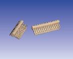
most common connectors we use to work with the signals of a printed circuit
board are those formed by a single row of contacts with a 1/10” pitch, in
Spanish also known as “conector poste”
The
assembly set is formed by a plastic terminal housing (female) a row of contacts
(male, straight or right angle) and individual terminals.
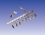
|
Terminals |
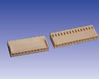
Female terminal housing |
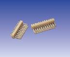
Male terminal header straight |
Male terminal header right angle |
|
|
|
|
|
|
|
|
|
Assembly procedure |
|
|
|
|
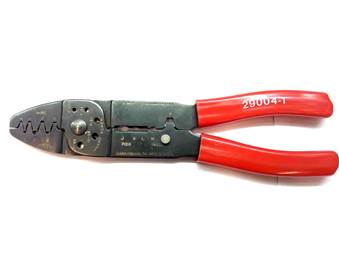
These terminals must be crimped (not solder) with
this AMP tool |
|
|
||
|
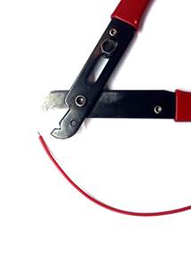
Strip the cable end, about 2 mm, and wrap the copper
wire |
|
|
|
|
|
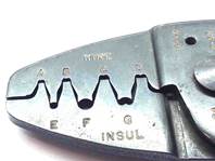
With the B shape, crimp the U shape of the terminal
with the copper wire. After that, crimp again using the A shape. Repeat with the plastic cover and the remaining U
shape, using the shapes B and A of the tool. |
|
|
|
|
|
|
|
|
|
|
|
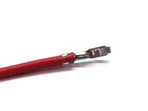
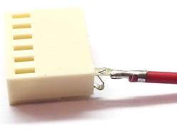
Finally, insert cable/terminal in the connector by
matching the metal retainer on the connector window |
|
|
|
|